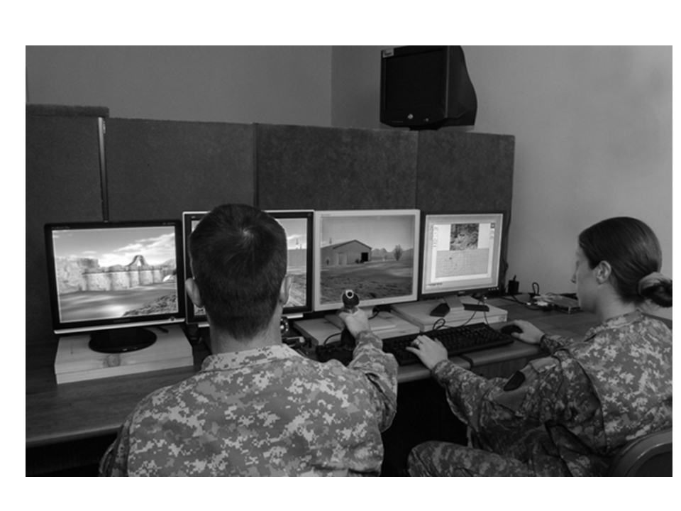
Presented are patents for aiding vehicle operations, such as:
(1) Adaptively optimizing camera display;
(2) Manual control of dual-image displays;
(3) Mitigating motion sickness;
(4) Motion sickness suppression systems and methods.
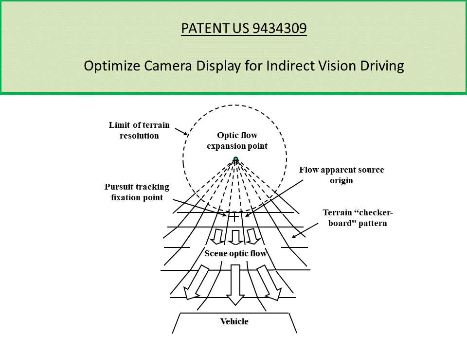
PATENT US 9434309:
Invention for adaptively optimizing camera display for indirect vision driving from predicted vehicle speed, as set by the display characteristics and the field-of-view of the camera (more)
A method and apparatus for predicting vehicle speed during an indirect vision driving task as determined from the camera return for the road conditions. A further method and apparatus for adaptively optimizing the display of a camera return during an indirect vision driving task based on an operator’s perceived vehicle speed as set by the display characteristics and the field-of-view of the camera with the predicted vehicle speed. A further method and apparatus for using the perceived speed as a driving task aid, in particular, as an electronic aider for optimizing the driving scene display characteristics of scene compression and camera field-of view. In this manner, the invention adjusts the perceived speed in order to match the operator’s cognitive flow to the control dynamics needed by the operator for the task. The invention has application to autonomous driving where manual intervention is incorporated during critical events for particular tasks; and with limited display space within the vehicle, the display format is adjusted by the invention according to the operator’s task needs.
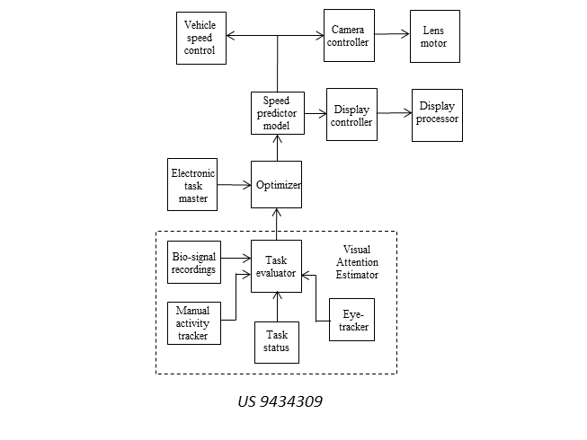
The invention adjusts the perceived speed of the vehicle to match the cognitive flow needed for the control dynamics of the operator for the task, by control of the speed of the vehicle and the camera return. The figure is a block diagram of the invention as a real-time adaptive aider, where the optimizer with input from the electronic task manager on the intervention task requested and the estimated time available, and input from the visual attention estimator about the attention state of the operator, computes with a performance estimator, the expected cognitive loading flow rate and the corresponding optimal perceived speed that would be compatible with the control dynamics needed for the requested task, and outputs control signals to the video display controller for the display processor on the driving scene display size and location, to the camera controller for settings of the camera lens motor for the FOV, and to the vehicle speed control for adjustment of the vehicle speed.as determined by the camera return settings for the road conditions.
The patented method for estimation of the speed of the vehicle for indirect vision and the expected resulting driving performance is further described in the research paper: Estimating expected performance for indirect-vision driving (more)
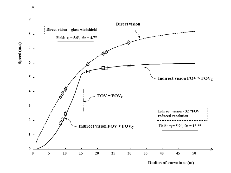
The figure shows the speed estimated by the patented method plotted as a function of the radius of road curvature with data points overlaid from a field study; the estimated and measured points are in close agreement. The figure plots the estimated speed for direct vision driving with an unlimited FOV, and that for indirect vision driving with a camera system. Note the break in the plot at about 16-meters where the camera FOV equals the critical value that is needed to see the optical flow origin. The view of the optical flow is limited for smaller radii resulting in a marked decrease in driving speed.
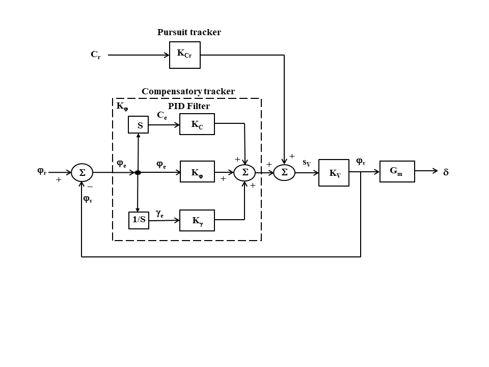
The performance estimator incorporates a driver steering control model with pursuit tracking of the path ahead to implement feed-forward control, coupled with compensatory correction of the path pursuit tracking. In the compensatory tracking, the control gain may be a filter configured as a PID controller with an output signal comprised of the weighted sum of the curvature, heading, and lateral offsets as the compensatory tracking correction. The weighted sum of the pursuit and compensatory tracking outputs is a manual motor control set point for the vehicle heading as the control signal to the human motor skills processor for setting the steering wheel offset; the steering wheel control is an acceleration control and the error rate is an anticipatory lead input.
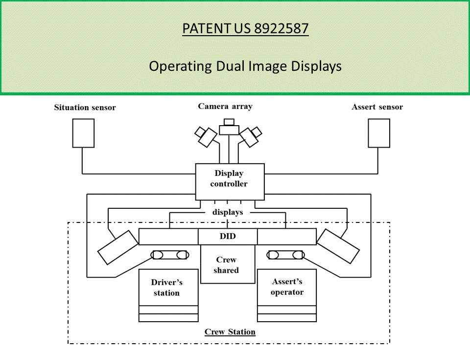
PATENT US 8922587
Invention is an operating system of dual-image displays in a manned vehicle crew station for multiple crewmembers, where the displays are of different information and visual content depending on the viewing direction. (more)
A dual-image display provided for use in a manned vehicle crew station and a display operating system for at least two crewmembers, each who may interact independently with the display using touch screen buttons, switches, or hand controllers. The display enables the simultaneous display of different information and visual content depending on the viewing angle or direction. In one embodiment, a video display system for use by crewmembers in vehicles may include a display monitor comprising a common display driver configured to provide separate virtual displays to at least two crewmember users, and one or more activators operatively associated with the users, wherein a further embodiment, the activators are based on hand bound RFID technology enabling touch free screen control.
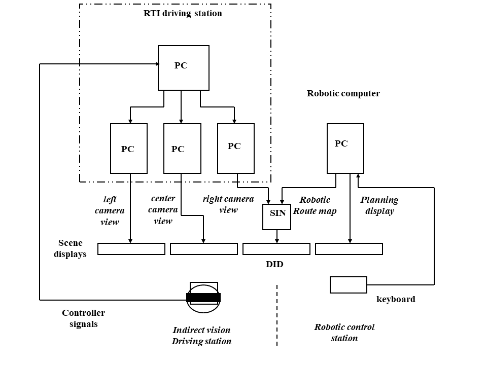
Schematic of crew station with a dual-image display (DID) shared by two crew members with the left side for indirect vision driving from forward looking central and side view camera returns, and a robotic control station of tele-operated units. In this configuration, the DID provides the right camera return image to the vehicle driver and a robotic route map to the robotic controller.
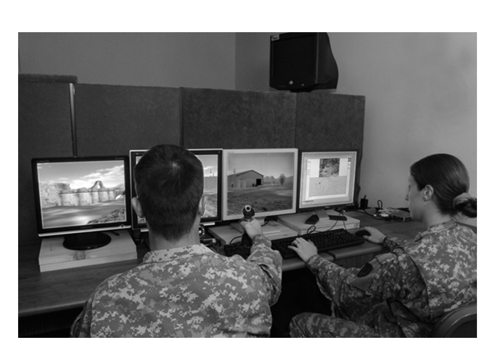
A view of two-person crew station mockup with a driver and robotic operator; the DID is the third display from the left. From this view, the display shows the right camera image to the driver; the robotic operator sees a planning map on the display.
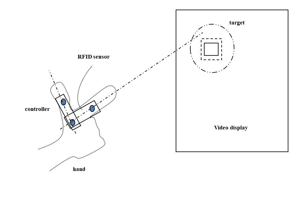
Patented are methods for multiple operators to operate a dual-image display without manual interference between operators. In one embodiment, the display activators are hand bound short range radio frequency identification system (RFID) tags attached to a hand glove to enable touch free screen control. In the figure shown, the tags attached to the glove thumb, knuckle, and index finger are used to sight on a displayed element (i.e., icon), which is grasped visually by closing the thumb and index finger to select the element. Here, the operator pointing his hand toward a display element with a virtual touch cueing zone, may use his foveal vision to move the crosshairs within the capture zone of the element by hand rotation and then closes his thumb to his finger to designate selection. With the RFID system operative with the display driver and the particular operator identified by the RFID return, the operator may cause operations on the element as needed.
PATENT US 8708884
Invention for mitigating motion sickness using a compensatory modulator with a display controller to adaptively mitigating motion sickness in an operator. (more)
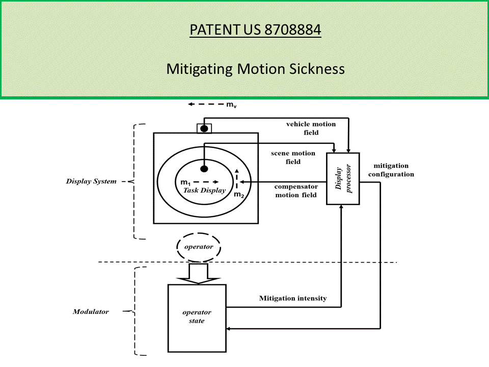
The invention describes methods and apparatus for adaptively mitigating motion sickness in an operator operating a video display. In some embodiments, a compensatory modulator for use with a display controller included in a system to adaptively mitigating motion sickness in an operator may include one or more inputs to receive at least one of physiological measurements of the operator or operator activity behavior from one or more monitoring devices, and a motion sickness expert system configured to (a) determine a cognitive state of the operator based on the received inputs, (b) compute mitigating display parameters based on the determined cognitive state of the operator, (c) output the computed mitigating display parameters to the display controller.
A motion sickness mitigation system is depicted in the figure with a compensatory display system for suppressing motion sickness and a modulator of the intensity of such a display for adaptive compensation. The compensatory display system consists of a display device with a task display and a motion sickness compensatory display, with the movement (m2) of the image displayed in the compensatory display determined by a compensatory engine via control signal based on the movement (m1) of the task display image, and the movement (mv) of the display device as measured by accelerometers. The compensatory engine determines a display format to maintain an inertial reference frame for the display from the accelerations and angular velocities both physical and visual sensed by the operator viewing the displayed scene. The compensatory modulator sets the intensity in accordance with the motion sickness state of the operator as determined by a motion sickness assessor with an embedded electronic expert system on motion sickness from activity behavior and physiological measurements and display settings feedback from engine. Here, at least one embodiment of the expert system incorporates a model of the symptomatic stages of motion sickness and in particular incapacitating motion sickness as related to the behavior and physiological measurements. The modulator computes the mitigating display parameters and outputs the parameters to the display controller.
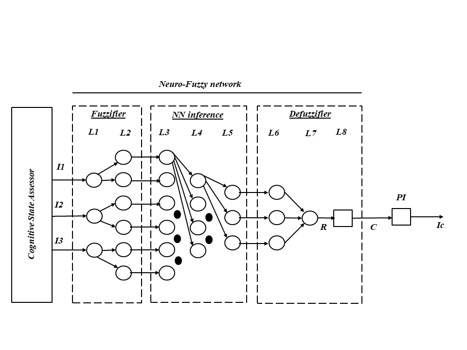
A schematic of the motion sickness assessor included in compensatory modulator, where the motion sickness assessor includes a cognitive state assessor with inputs, in series with a neuro-fuzzy network circuit. The neuro-fuzzy network circuit consists of a fuzzifier stage, a sickness inference machine (e.g., a neural network (NN) inference machine), and a defuzzifier. The inputs to the state assessor consist of task related observables such as input from eye-gaze estimator, input from facial image processor, and input from task behavior estimator. The outputs from the state assessor to the fuzzifier, consists of the degree of state estimates for self-referral (I1), task immersion (I2), and task confounded (I3). In some embodiments, the fuzzifier consists of two layers, with input layer L1 and output L2 of the linguistic level of the states. The neural network inference machine, which in some embodiments may be in the form of a feed-forward propagation three layer network (input L3, output L5) with a hidden layer (L4), operates upon the input according to production rules for network connector weights between layer nodes. The production rule outputs are converted as linguistic values inputs (at layer L6) by the defuzzifier into a signal R (layer L7) and then into the rate control signal C following crisping at layer L8. The output C of defuzzifier (and neuro-fuzzy network circuit) may be input to a proportional-integrator (PI) with display control signal (IC); with the integral reducing sensitivity to transients in motion sickness response.
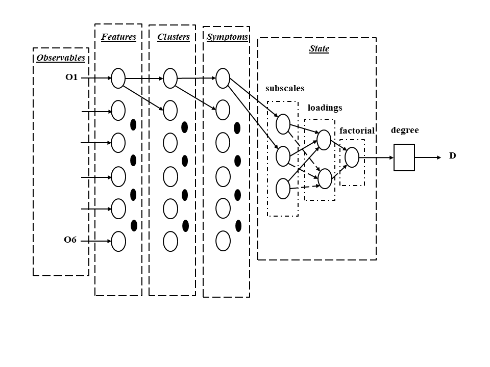
The cognitive state assessor is composed of three sub processors with one for self-referral (from motion sickness), another for task immersion and still another for task confounding, where a sub-processor consists of stages for observable inputs, a feature classifier for the inputs, a clustering processor with outputs to a symptoms processor, and a state classifier. The state classifier constituted as an expert system may further consist of a subscale rater, a loading computer, and computation of factorial values. In some embodiments, the factorial value is mapped to the degree of cognitive syndrome condition, with degree output D as input to the fuzzifier of the motion sickness assessor. In at least some embodiments, the feature, cluster, and symptom processors may be configured as neural networks.
The expert systems of the state classifier estimate the cognitive state as degrees of one or more of self-referral induced by motion sickness, task immersion, and task distraction by matching clusters of such measurements to a framework for equivalent subjective ratings of symptoms of the state conditions coupled to a structure incorporating a state model. Here, subjective sub-scales are frames for the features of the observables the values of which are the scale ratings; the relations among the scalar frames construct the symptoms, and from these in turn the factorial component are computed using the factor loadings, the value of which is used to estimate the subjective degree of the cognition state. The assessment process isolates pertinent features of the observable measures, forms clusters of weighted features, fits clusters to the state symptoms, determines equivalent subjective ratings of the symptoms, estimates state components from the factorial loadings, and computes the degree of the subjective state.
PATENT 7918781
Systems and methods for suppressing motion sickness in operations of video displays (more).
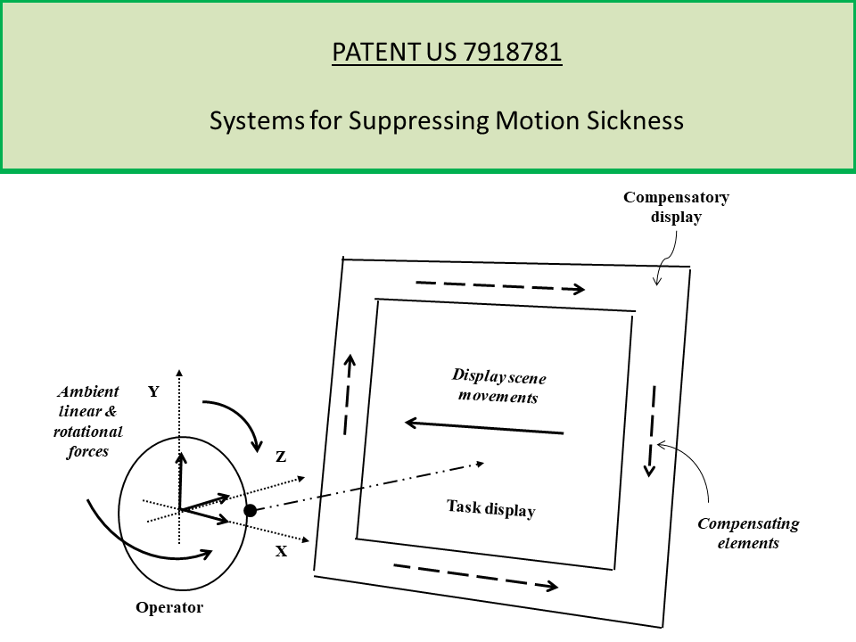
Systems and methods for suppressing motion sickness are patented with an exemplary system comprising a display driver and a display controller. The display device is operative to display a first image and a second image. The display controller communicates with the display device and is operative to control display of the second image such that the second image moves relative to the display device in response to at least one of: motion of the first image relative to the display device, and motion of the display device.
The figure schematically depicts the relationship between an operator viewing an embodiment of a display device and the scene and compensatory fields of that display device, where the scene image may be from a camera return and the compensatory fields are such as to suppress motion sickness induced by viewing of the scene. Specifically, an operator is viewing a display device, while experiencing linear and rotational forces induced by the physical environment. In this embodiment, the display device includes a central task display showing a scene field with scene images that are moving (here to the left as indicated by an arrow), and a peripheral compensatory field displaying compensating images that are moving laterally to the right and vertically (indicated by broken arrows). In this depiction, the compensatory displays are designed to compensate for the scene display in such a manner as to suppress the motion sickness induced in the operator by the conflict between the visual scene motion and that caused by the ambient forces.
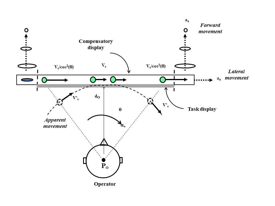
The figure depicts a top view of the movement fields of the compensatory images for suppressing motion sickness in a camera scene and specifically illustrates the velocity flow that would result from the compensatory display driver as determined from the image engine for the scene accelerations and those on the operator. For the purposes of illustration, the velocity flow of the elements for the top horizontal compensatory display is shown for lateral movement; similar displays are shown laterally for vertical movement, and elements are shown as changing size for conflicts in forward movement. The figure shows a compensatory velocity uc’ about the y-axis in response to discrepancies in rotational acceleration, a linear velocity uz for forward acceleration, and linear velocity ux for sideward accelerations. The solid vectors denote actual velocity flow and broken line vectors denote apparent velocity flow to the operator. Similarly, the compensatory elements are denoted as filled circles and the apparent elements by unfilled circles for simplicity.