Presented are patents for:
(1) Tracking eye-gaze;
(2) Retinal display eye tracker design.
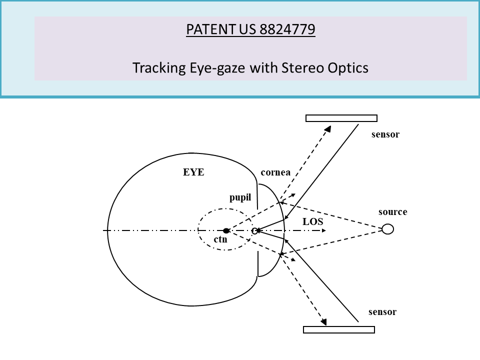
PATENT US 8824779
Invention in one configuration as a single lens stereo optics design with a stepped mirror system for tracking the eye, locates structures of the eye in the coordinate system of the optical unit, and computes the optical axes and from that the line of sight and the torsion roll in vision. (more)
The invention isolates optical features in separate stereo images, locates the pupil in the eye, matches features to a template centered on the pupil, mathematically traces refracted rays back from the matched points through the cornea to the inner structure, and locates these structures from the intersection of the rays for the separate stereo views. Having located in this way structures of the eye in the coordinate system of the optical unit, the invention computes the optical axes and from that the line of sight and the torsion roll in vision. Along with providing a wider field of view, this invention has an additional advantage since the stereo images tend to be offset from each other and for this reason the reconstructed pupil is more accurately aligned and centered.
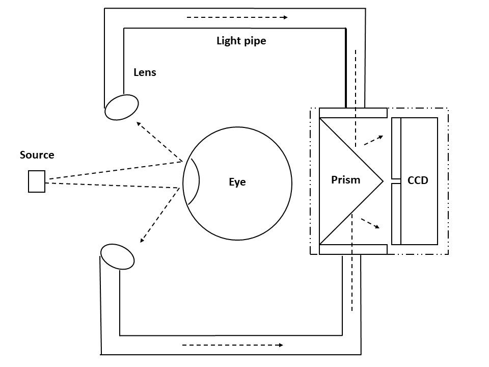
Invention here configured as a single lens stereo optics design with a stepped mirror system for tracking the eye.
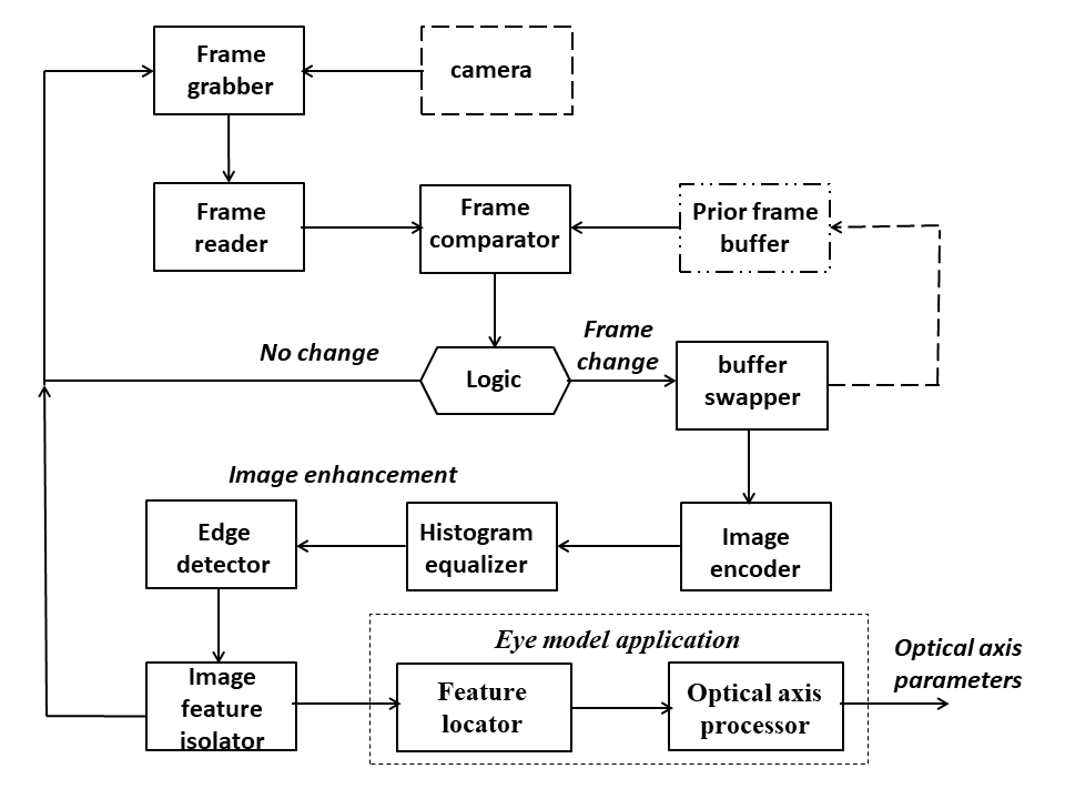
Image processing for camera image capture, image enhancement and feature isolation, and computation of optical axis parameters by feature processing from features located in eye for determining the line of sight and the torsion roll in vision.
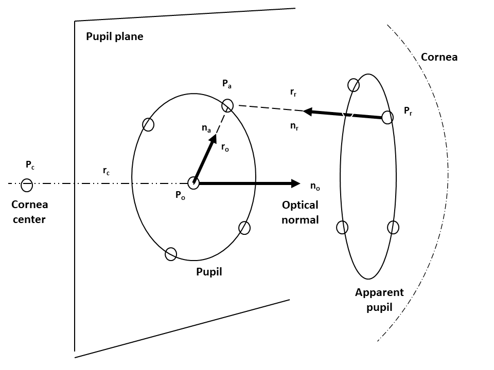
Feature processing isolates landmark features in the separate images, locates the pupil in the eye, matches landmarks to a template centered on the pupil, mathematically traces refracted rays back from the matched image points through the cornea to the inner structure, and locates these structures from the intersection of the rays for the separate stereo views.
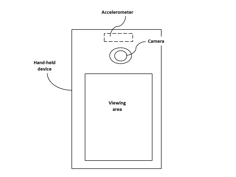
The invention has further application to hand held electronic devices such as cellular mobile phones or smartphones and data pads among others to track the user’s interest in device video display icons; particularly, those devices with an embedded camera system such as a single or multiple cameras for tracking the eye gaze on the device with facial recognition software for locating the eye to be tracked and an accelerometer to locate the phone relative to the user.
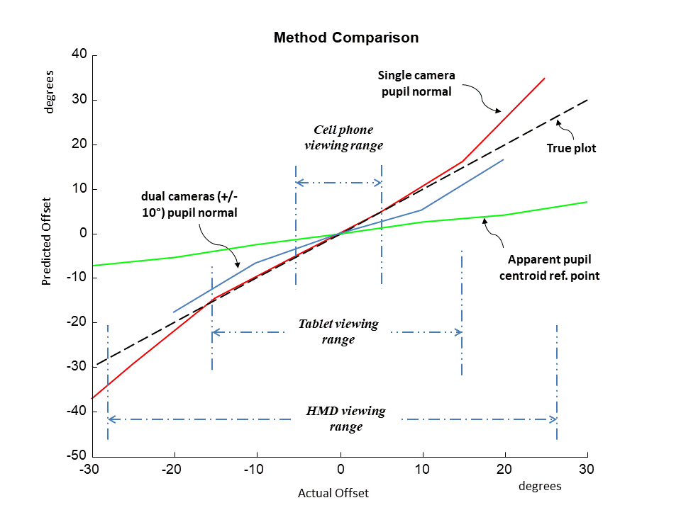
Performance tests shows excellent agreement of the viewing direction for a prototype design with the single camera over a 30-degree viewing range, and predictable agreement for a dual camera configuration without need for calibration. In contrast, the apparent pupil centroid method presently used in commercial trackers is in need of calibration by the user before application. The results are based on images of a medical standard artificial human eye centered on a calibrated turn-table with offset as the angle between the camera face-normal and the optical axis of the eye.
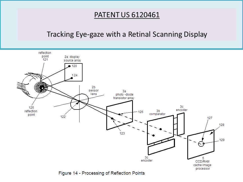
PATENT US 6120461
Tracking the human eye with a retinal scanning display (more).
NOTE: The patent is fee expired, the technology being presented is of interest for inclusion as an alternative design.
A retinal scanning display, an active-pixel image sensor array, and an image processor track the movements of the human eye. The scanning nature of the display acts as a sequential source of eye illumination. The active-pixel image sensor array is directed toward the cornea of the eye through a matrix of micro-lens. The sensor is integrated with a comparator array which is interfaced to bilateral switches. An element address encoder and latch determines the sensor element which reaches maximum intensity during the raster scan period of the display driver. Over a display field refresh cycle, the invention maps the corneal surface to a data table by pairing sensor activations to the spectral reflections from the cornea of the sequenced source lights.
In a particular embodiment, at each raster-scan pulse, the electronics accumulate pixel-wise the intensities of the sensor elements to activate a charge-coupled device (CCD) array for acquiring an image of the eye from the diffused reflections. This is done for those sensor-pixel elements which have intensities that are less than that for specular reflection, as determined by an array of limit comparators. The comparators control an array of transistor-driven emitters which are mapped one-to-one to the CCD array through an array of one-of-two switches. The intensity limiting precludes specular wash-out of the image. In another embodiment, a memory cache replaces the CCD array, and the emitters are replaced by analog-to-digital converters in series with digital read-adder-write circuits.
The invention computes at the display field refresh cycle pulse, a three dimensional model of the eye from the source to sensor pairing table and the eye’s image. First, the image processor, embodied as a stack of very-large-scale-integrated (VLSI) circuit arrays, isolates features for the pupil, retinal fundus, and iris. The invention next computes a three-dimensional model of the cornea by applying an ophthalmometric ray tracing technique to the pairing table. The invention then computes optical locations for the isolated image features with the ophthalmomatric ray tracing and the corresponding image locations and the pairing table.
Using a best fit to a three dimensional model of the eye, the invention computes the optical origin and the optical and median axes from the values for the corneal and internal features. These include the corneal optical center, the corneal surface center and axes, the pupil optical center, the pupil image orientation, the capillary network of the retinal fundus, and the sphincteral pattern of the iris. Finally, the invention computes the viewing origin and axis for the eye from the optical origin and axis, and the median axes. The invention may be used to measure visual gaze direction, point of regard, and the duration of the gaze fixation.